All valves perform a duty. Their ability to perform varies by valve type and internal design features and materials. In addition, knowledge and experience play a significant part in any successful installation.
Accurate descriptions and consistent communication regarding the specifications of the valve required, and the attributes of the application it needs to perform within, have always played a big role in valve selection. Unfortunately, the valve industry has consistently been too casual with language, allowing subjective words to serve as official terminology, leading to a false sense of security for the buyer and the seller.
Two phrases that are commonly used — “tight shut-off” and “high-performance” — sound good, but neither is objective or measurable.
Knife gate valves are perhaps the worst offenders in offering security without any basis of fact. The original knife gates were designed to be a low-cost valve with moderate isolation abilities of low pressure (<10 Barg; 150-psig), low cycle (<50/year). The name “knife gate” should normally indicate that the valve was designed to cut like a knife. The fact that the original patent never had that feature as a design requirement is curious, but it was a clever marketing concept. If you look closely at the original knife gate valve design, you will see that the sharp knife edge was not there to cut, it was there to wedge. In fact, the first knife gate valve should have been given the name Single Direction Wedge Gate.
The first true mining application knife gate, patented by Clarkson, also has a sharp knife gate tip; but again, it is not for cutting, it is for separating and dividing the two sleeves.
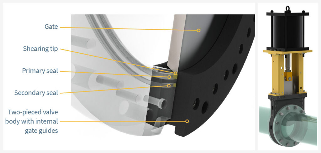
The invention of the Guided Shear Gate valve (GSG) came about largely through the frustration with the other types of knife gate valves, none of which could cut to handle heavy slurries effectively. The inventor used the concept of a guillotine, or shear, to effectively cut though any solids, provided there was sufficient thrust. The gate tip was fashioned as a chisel tip and a 2-piece machined body guided the gate to its shear point and eventual full travel into the resilient and secondary metal seat. The gate is prevented from deflecting upstream or downstream and seals axially against the resilient seat, ensuring bi-directional zero leakage. Now fibrous, suspended, or dissolved solids slurries could be handled routinely.
The disadvantage of the GSG is that the body is wetted by the process, unlike the Lined Knife Gate valve or the Push-Through valve. In these valve types a liner or the elastomeric sleeves protect the pressure retaining body from the process and therefore can be selected as inexpensive non-corrosive resistant materials like Ductile Iron or Carbon Steel.
However, in actual use in hydrometallurgical applications, neither Lined Knife Gate valves or Push-Through valves have proven to be a viable solution. In fact, both have been hugely unsuccessful in the facilities that used them. The original gains of cost savings were completely consumed by the massive failures that occur during the valves’ operations. Lined valves are attacked externally from stem leakage and Push-Through valves discharge acid solutions to atmosphere and nearby piping, equipment, or the plant floor. The Push-Through’s discharge containment feature is ineffective or costs so much that it adds far more to the final price tag compared to simply selecting the proper knife gate valve in the first place.
The GSG’s general selection process is reasonably simple:
- Choose a body material equal to, or more resistant, than the pipe it is installed in (if metal piping) or a body construction that has a <20 mpy (0.508 mm/yr) corrosion factor.
- Choose a gate material that has a corrosion resistance of <1 mpy (0.0254 mm/yr).
- Select a corrosion and temperature resistant resilient elastomer or polymer (we use a resilient fluoropolymer as a standard) and select an operator or actuator that can handle the changes in thrust from the precipitation of solids.
By studying the various deposits in hydrometallurgy valves, we have learned to treat the moving surfaces of the valve with a finish that reduces the effect of deposits on thrust increase, while being very conservative in actuator or operator selection. The treatment involves a surface preparation with a baked-on fluorocarbon finish which makes the surface slippery to the deposit. One extreme example is a 250mm (10-inch) Class 300 Titanium Gr 12 Guided Shear Gate valve mounted with a 550mm (22-inch) pneumatic cylinders so they could cut through a solid deposit of 25mm of nickel sulphide scale. They did, consistently, when required!
Hydrometallurgical process plants are often challenging environments for valves due to corrosion occurring outside the pipe. The GSG has a design that helps reduce the negative effects from external corrosive sources. The manual GSG version has a non-rising stem, protected by Lexan covers on the bonnet. These ensure that the stem and stem nut stay clean and available to translate the human torque into thrust efficiently. When automated with pneumatic, hydraulic, or electric-hydraulic cylinders, the cylinder rods are also protected, as are the limit or proximity sensors.
Conclusion
The GSG is designed to be a plant asset, to be maintained and serviced, and to provide consistent and reliable isolation of the various processes the plant needs to remain safe, profitable, and environmentally sound. Chosen correctly, the GSG can radically reduce OPEX, and if carefully selected during initial design, can even contribute positively to the CAPEX limits new projects are held captive to.