There are many types of valves used to isolate process flow. Each valve type has its own ability when it is fully closed and in isolation mode. The degree of tightness varies with valve type, make, media, differential pressure, temperature, and time in service. Some valve types or special preparations have unequal isolating abilities depending on the flow direction while isolating.
Understanding how valves isolate, especially with challenging applications, can help one choose the appropriate valve technology. All isolation valves are bidirectional, that is, they can seal from either flow direction. However, bidirectionality can add some isolation wrinkles and thus needs further explanation.
Many valves cannot isolate equally from either direction. Think of a car; it can go backward and forwards, just not equally well. Isolation ability, the ‘tightness’ of the closure, is a misunderstood subject in the valve industry. It has been made more complicated due to the valve’s ability to handle bidirectional flow at shut-off while isolating.
Isolation Valve Types and Abilities
The valve industry commonly uses valve test standards to validate the tightness performance of isolation valves. API 598, MSS-SP-61, and ISO 5208 are three common standards that are typically used. Resilient ‘soft’ seated valves are generally expected to seal perfectly. That is, show no through leakage during the test period using the benign test media (usually air, nitrogen, or water) at the test’s differential pressure. Metal seated valves above 2” have an allowable leakage rate, although there are some metal seated designs which are as tight as soft seated valves and remain that way in service far longer and in far more challenging environments.
Most often, the isolation valve’s isolating ability is not identified by the test standards, but by another standard like FCI 70.2 using roman numerals as qualifiers, or a subjective term like tight shut-off (TSO) or bubble-tight shut-off (BTSO). The irony is that FCI 70.2 is a standard for control valves, not isolation valves, and has no ‘tightest’ i.e., zero leakage standard. All classes allow leakage, while TSO and BTSO have no definition of how they are achieved or what tests are performed.
Zero-through leakage of an isolation valve is the ultimate or highest performance. Although some argue that it is scientifically technically impossible, it is possible to demonstrate that it is practically possible. To do so one must be careful in selecting the proper valve technology for the application, and consider whether the valve will be isolated from one or two directions, whether it needs to be bidirectional, and if yes, equally.
| Valve Type | Directional | Preferred Install | Tightest Shut-Off |
|---|---|---|---|
| Ball — Floating | Equally & Fully Bidirectional | No | Yes |
| Ball — Integral Fixed Seat | Unequally Bidirectional | Yes | Yes |
| Ball — Trunnion | Equally & Fully Bidirectional | No | Yes |
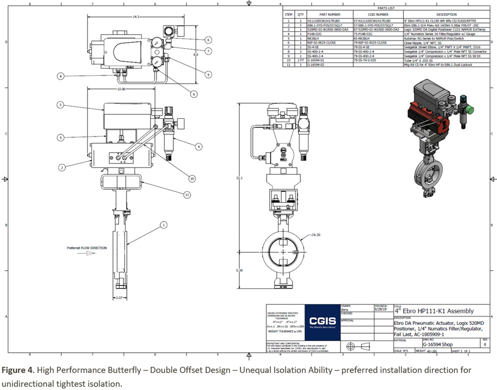
| Butterfly — Offset Shaft | Unequally Bidirectional | Yes | Yes |
| Butterfly — Resilient Seat Centric Shaft | Equally & Fully Bidirectional | No | Yes |
| Butterfly — Triple Offset | Unequally Bidirectional | Yes | Yes |
| Gate — Parallel Slide | Equally & Fully Bidirectional | No | No |
| Gate — Wedge | Equally & Fully Bidirectional | No | No |
| Globe | Unequally Bidirectional | Yes | No |
| Knife Gate — Conventional | Unequally Bidirectional | Yes | No |
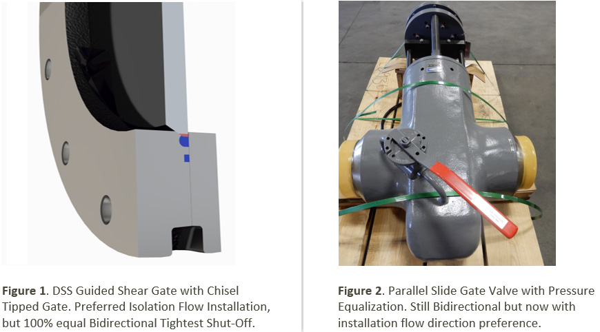
| Knife Gate — Guided Shear Gate (GSG) | Equally & Fully Bidirectional | Yes | Yes |
| Knife Gate — Push-Through | Equally & Fully Bidirectional | No | Yes |
| Knife Gate — Slide Through-Gate | Equally & Fully Bidirectional | No | No |
| Plug — Lubricated | Equally & Fully Bidirectional | No | Yes |
| Plug — Sleeve-Lined | Equally & Fully Bidirectional | No | Yes |
The Problem
The understanding of valve isolation performance is not universally clear. Many believe that all isolation valves have similar abilities to stop the process flow. Unfortunately, this is not the case. The topic is made more complicated by the valve industry’s lack of objective and clear descriptions of isolation performance. This becomes clear when one considers how often they have heard or used Tight Shut-Off, Bubble- Tight, or even zero leakage without knowing how they were defined, tested, or designed. How tight is tight?
While it is beyond the scope of this document, isolation quality is a very deep subject CGIS has been involved with for over 40 years. CGIS aims for zero leakage isolation performance as the practical target when selecting the proper valve technology. This term includes fugitive emissions and leaks for body joints as well. The isolation valve must be capable of preventing internal media to escape to the atmosphere or downstream of the closed valve. For a very detailed example of the nuances of perfect or imperfect isolation, see “Tightness of Triple Eccentric Butterfly Valves”, available on emailed request.
Isolation valves generally fall under two categories: position seated, or force-seated (torque for rotary and thrust for linear valves). A wedge gate valve is position- seated, any variation in line pressure will have no influence on the gate valve’s sealing ability. A centric resilient-seated butterfly valve shut-off capability is dependent on the rotational position of the disc and will not be affected by line pressure. A force-seated valve, such as a globe valve, triple-offset butterfly valve, floating ball valve, or conventional knife gate valve uses mechanical force to provide shut-off. This force is provided by the rotating stem in a globe valve, the line pressure acting on the closed ball in a floating ball valve, or in the case of a triple-offset butterfly valve, the torque applied to the offset stem forcing the conical disc into a conical seat.
ADAMS Triple Offset Butterfly Calculation of Opening/Closure Torque
|
Required Opening Torque to unseat the valve from closed position |
72,875 in-lb. |
|
Required Closure Torque to seat the valve in closed position |
72,875 in-lb. |
|
Torque values in % of calculated input torque |
|
|
100% |
Bidirectional tightness (equal Zero Leakage isolation) |
|
90% |
Bidirectional tightness and Leakage Class V (not Zero Leakage) |
|
80% |
Bidirectional tightness and Leakage Class IV (not Zero Leakage) |
|
80% |
Unidirectional tightness (not Zero Leakage) |
|
72% |
Unidirectional tightness and Leakage Class V (not Zero Leakage) |
|
64% |
Unidirectional tightness and Leakage Class IV (not Zero Leakage) |
Along with the often-misunderstood quality of the isolation valve’s abilities, there are also often challenges with clarity when the direction of isolation is included. Many applications are always unidirectional, the process flow can never be in the reverse direction, for example, a Tank Drain or a Pump Discharge Isolation Valve. There are applications where the piping system allows process flows to travel in both directions. It is important to know the details of the application so the best valve technology can be selected.
Typically, directions in pipes are referred to as Upstream and Downstream, or high-pressure or low-pressure. This is applied to the valve’s installation direction. In the case of a pump isolation valve, suction, or discharge, the direction of isolation is towards the pump, as it is only isolated when the pump is idled and shut down. Valve installation direction for low pressure, low cycle, and benign fluid application is less important than it is for severe service applications where the isolation valve’s abilities are challenged; in this situation all aspects of valve technology selection become critical.
A typical high-pressure boiler vent or drain valve is always going to be unidirectional if it drains or vents to the atmosphere, but some high-energy systems have complex downstream piping where the pressure may equal or exceed upstream pressure at some point in the process.
The Solution
As per the saying ‘the application dictates the valve,’ every isolation valve application requires a full analysis of what its life cycle will entail. Not only operating pressures, temperatures, media, materials of construction, operation or automation, and connection to the pipe, but also what is the function of the isolation valve, how long does it need to be capable of isolating, and what must the minimum quality of isolation be during that operating period?
Conclusion
Understanding how isolation valves work and how the process flow acts upon them, increases the opportunity for success. Most processes are linear in all, or the majority of their design so unidirectional sealing valves are acceptable if they are installed in the way recommended by the manufacturer. For those specific applications that do require bidirectional sealing, one must understand the differential pressure values in both isolating directions. For a very limited number of applications, fully equal bidirectional valve designs must be selected, while for most other applications, bidirectionality is not a requirement.
Different valve designs offer varying isolation abilities as well as varying flow direction isolation. Some valve designs are naturally equal, like floating ball valves, where flow direction has no preference on the installation, while some designs have a definite preferred flow direction and unequal isolation ability like offset shaft or triple offset butterfly valves, and need to be installed preferentially. Others have an equal isolation ability but a preferred installation direction like the GSG knife gate valve where the optional use of a single-wear ring will require the ring to be located on the upstream side (for one-directional services), or where solids pushed off by the gate tip should be disposed of ‘downstream.’
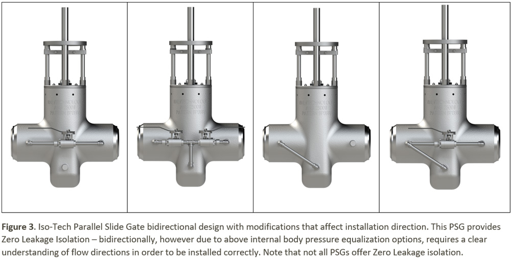
Further considerations to valve installation occur when special options are supplied to otherwise equally bidirectional isolation valves types like parallel slide gates and floating ball valves, as seen in Figures 2, 3, 5 & 6.
Figure 3 shows the optional addition of pressure relieving by-pass valves which now convert the standard equally bidirectional valve with any installed direction into one with a preferred flow direction.
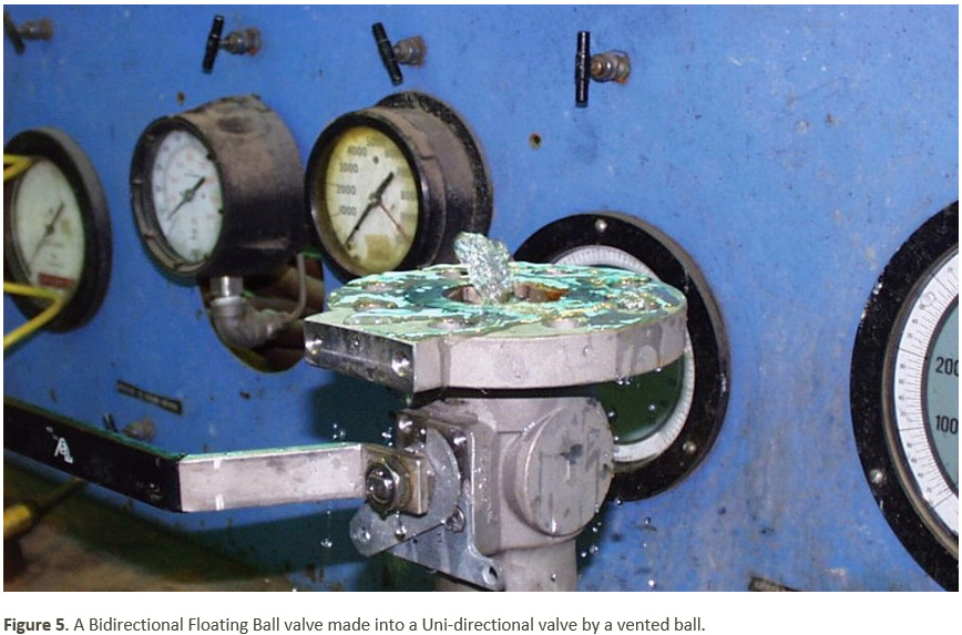
Figure 5 demonstrates when a floating ball is prepared for service with an expansive fluid like anhydrous ammonia. This service requires a method to release the volume of expanding fluid to a safe ‘upstream’ side of the otherwise equally bidirectional isolation valve; a hole is drilled in one side of the ball which is 90 degrees across from the open port which allows the expanding fluid to flow safely back upstream.
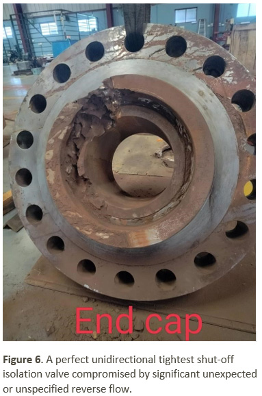
Figure 6 is a graphic example of getting bidirectionality wrong. This metal seated ball valve is ideally suited for isolating a high-pressure iron ore slurry concentrate piping system. Its standard design is for isolation where the end cap is on the ‘downstream’ side of a unidirectional pipeline. If and when the piping system has significant reverse flow, a modification of the upstream floating seat and belleville load spring is employed and the valve can be successfully deployed. Unfortunately, this bidirectional flow regime where the valve was installed was not communicated, and in less than a day an expensive asset was heavily damaged.
Lesson learned: ensure all process design conditions are known before ordering valves, even seemingly minor nuances.